- Home
- Products
- Electric Wire and Cable
- Equipment wire
- Multipair Cable
- Cable type OKIFLEX
Multipair Cable
Cable type OKIFLEX(UL STYLE NO.2935 80°C 300V 2384 60°C 30V)
Overview
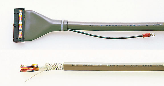
Terminal treatment example
The core wires are twisted together in pairs to prevent signal crosstalk. The terminal core wires can be laminated flat for connection between devices.
Features
- The core wires have been pair-twisted to prevent crosstalk. A shielded type is also available upon request.
- For connection between devices, this model can be cut to the specified length; and the terminal core wires can be laminated flat (1.27 mm pitch) and batch connected to an IDC connector using batch insulation displacement contacts.
- The core wires can be identified with dot marks, which is useful during soldering, crimping, etc.
- This model is robust thanks to its round cable structure with PVC coating.
- This product is environment-responsive.This product is RoHS compliant.
Applications
This model is ideal for the internal wiring of computers,terminal equipment, communication instrument,controllers, office equipment, etc. as well as for the wiring connections between devices.
Shape
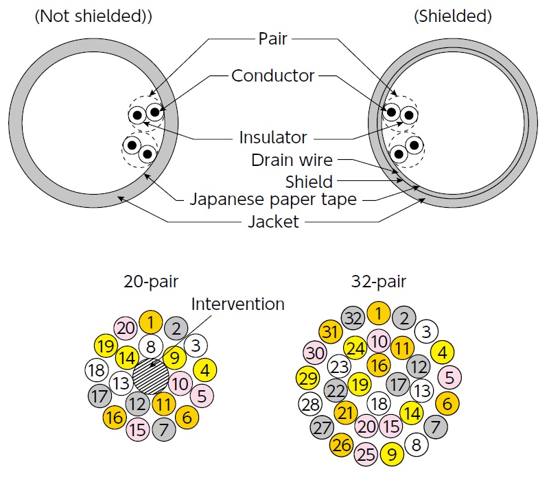
One line of intervention is used for 5/8/17/20 pairs Two lines of intervention are used for 10-pair.
Specifications(Shielded)
| Type I | Type II | |
|---|---|---|
| Conductor resistance Ω/km (20°C) | 222 or less | 222 or less |
| Insulation resistance MΩ-km (20°C) | 1 or more | 1 or more |
| Dielectric Strength V/min | 2000 | 500 |
| Capacitance pF/m *1 | Standard 89 | Standard 168 |
| Characteristic impedance (Ω) *1 | Standard 73 | Standard 48 |
| Propagation delay ns/m *1 | Standard 5.6 | Standard 5.8 |
| Near-end crosstalk % *1 | Standard 4.6 | Standard 6 |
| Flame Resistance | VW-1 | VW-1 |
| UL STYLE NO. | 2935 | 2384 |
- *1 : The measurement for capacitance, characteristic impedance, propagation delay and near-end crosstalk are all grounded except the measurement target pairs.
Product name notation
7/0.127 (a)P HRV-(b)-UL SB Type I *3
7/0.127 (a)P HRV21-(b)-UL SB Type II *3
- *2 : Enter the number of pairs in (a) and with/without shield in (b) as shown below.
V……Not shielded SV……Braided shield - *3 : SB indicates the jacket color symbol (warm gray).
Configuration Table
| Number of pairs | Number of cores | Insulator (pcs/mm) | Insulator outer diameter (mm) | Jacket thickness (mm) | Jacket outer diameter (mm, shielded) *4*5 | Packaging unit | ||
|---|---|---|---|---|---|---|---|---|
| Type I | Type II | Type I | Type II | |||||
| 5 | 10 | 7/0.127 *6 (AWG28) |
1.10 | 0.80 | 1.0 | 7.3 | 6.3 | 100 m (328 ft.) |
| 7 | 14 | 7.8 | 6.7 | |||||
| 8 | 16 | 8.8 | 7.4 | |||||
| 10 | 20 | 8.9 | 7.5 | |||||
| 13 | 26 | 10.1 | 8.3 | |||||
| 15 | 30 | 10.3 | 8.5 | |||||
| 17 | 34 | 10.8 | 8.9 | |||||
| 20 | 40 | 11.9 | 9.4 | |||||
| 25 | 50 | 12.9 | 10.4 | |||||
| 30 | 60 | 13.3 | 10.7 | |||||
| 32 | 64 | 14.0 | 10.8 | |||||
- *4 : The jacket outer diameter is for the shielded model. The non-shielded type is approx. 0.5 mm smaller.
- *5 : Shielded models use a drain wire (10/0.12).
- *6 : Conductors other than 7/0.127 (AWG28) are supported by UL STYLE NO.2464 300V 80 deg C(AWG26.24.22.20.18).
- Inquiries regarding materials, consultations, and technology
- Inquiry from Web: Inquiry form