- Home
- Products
- Electric Wire and Cable
- FA/Robot cable
- OFV cable
FA/Robot cable
OFV cable(UL 758 Style 2464 80°C 300V)

Overview
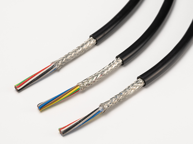
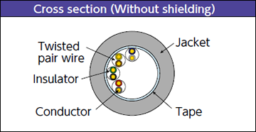
These cables are for fixed wiring and are compatible with a rated voltage of 300 V. Their small diameter gives them pliability and excellent routability.
Features
- Thinner PVC insulation results in smaller diameter cables, saving space during installation.
- Using low-hardness, flexible jacket material improves their flexibility and increases efficiency in wiring work due to the ease of handling.
- They also demonstrate durability in harsh environments where machine oil is spattered, such as in factory equipment.
- The lineup includes layer-stranded types and twisted-pair types, which can be used for a wide range of applications.
Product code indication
Without shielding : OFV (1) AWG × (2) C (2464)
With shielding : OFV (1) AWG × (2) C (SB) (2464)
(1): Conductor AWG size (2): Number of pairs(Please see the table below)
Without shielding : OFV (1) AWG × (2) P (2464)
With shielding : OFV (1) AWG × (2) P (SB) (2464)
(1): Conductor AWG size (2): Number of pairs(Please see the table below)
Specifications
Material and Structure
| conductor | Tin-plated, soft copper, twisting cable |
|---|---|
| insulator | PVC |
| Insulator identification | Depends on the core wire identification and configuration of core wires (pairs) |
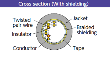
| Shielding | Braided Tin-plated soft copper wire(including drain wire) |
| Jacket material (jacket color) | Oil-proof PVC(black matte) |
| Flame retardancy | VW-1 |
Usage environment
| Application | Fixed and moving parts between equipment and within equipment indoors |
|---|---|
| Operation temperature range |
-10 to 80°C |
Lineup
| Shielding | Layer stranded type | Twisted pair type |
|---|---|---|
| Without shielding | Conductor size:24 to 20AWG Number of cores:2 to 30 |
Conductor size:26 to 20AWG Number of pairs:2 to 34 |
| With shielding | Conductor size:24 to 20AWG Number of cores:2 to 30 |
Conductor size:26 to 20AWG Number of pairs:2 to 34 |
Allowable bending radius
| Fixed part wiring | At least 4 times the cable outer diameter |
|---|
Applicable standards
UL 758 Style 2464(Rating:80°C、300V)
Jacket Marking*1

□:Conductor size(AWG) 26/24/22/20
- *1 : The printed information may vary depending on the date of manufacture and product type.
Special characteristics
Electrical performance
| Conductor cross-section area mm² | AWG size |
Conductor resistance Ω/100m(20°C) |
Insulator resistance MΩ-km(20°C) |
Withstanding voltage V/min |
|---|---|---|---|---|
| 0.14 | 26 | 134 or less | 10 or more | AC2000 |
| 0.2 | 24 | 92.6 or less | ||
| 0.3 | 22 | 60.2 or less | ||
| 0.5 | 20 | 38.1 or less |
Lineup : Layer-stranded types
Structure
| Conductor | Insulator | (2) Number of cores |
Without shielding | With shielding | *3 Allowable electric current A (30˚C) |
||||
|---|---|---|---|---|---|---|---|---|---|
| (1) AWG size |
sq. mm | Configuration wires/mm | *2 Outer diameter mm |
*2 Finished outer diameter mm |
Approximate weight kg/km | *2 Finished outer diameter mm |
Approximate weight kg/km | ||
| 24 | 0.2 | 11/0.16 | 1.12 | 2 | 4.3 | 19 | 4.7 | 27 | 4.5 |
| 3 | 4.6 | 23 | 5.0 | 32 | 3.9 | ||||
| 4 | 4.9 | 27 | 5.3 | 38 | 3.5 | ||||
| 6 | 5.6 | 37 | 6.0 | 48 | 3.2 | ||||
| 8 | 5.9 | 43 | 6.3 | 55 | 3.0 | ||||
| 10 | 6.3 | 51 | 6.7 | 65 | 2.7 | ||||
| 12 | 6.9 | 60 | 7.3 | 75 | 2.5 | ||||
| 16 | 7.5 | 75 | 7.9 | 95 | 2.1 | ||||
| 20 | 8.1 | 90 | 8.5 | 110 | 1.9 | ||||
| 30 | 9.4 | 125 | 9.8 | 145 | 1.7 | ||||
| 22 | 0.3 | 17/0.16 | 1.29 | 2 | 4.7 | 22 | 5.1 | 32 | 6.0 |
| 3 | 5.0 | 29 | 5.4 | 40 | 5.2 | ||||
| 4 | 5.3 | 34 | 5.7 | 47 | 4.6 | ||||
| 6 | 6.1 | 47 | 6.5 | 60 | 4.3 | ||||
| 8 | 6.5 | 56 | 6.9 | 70 | 4.0 | ||||
| 10 | 7.0 | 67 | 7.4 | 82 | 3.6 | ||||
| 12 | 7.6 | 80 | 8.0 | 95 | 3.3 | ||||
| 16 | 8.3 | 100 | 8.7 | 120 | 2.8 | ||||
| 20 | 9.0 | 120 | 9.4 | 140 | 2.6 | ||||
| 30 | 10.6 | 180 | 11.0 | 200 | 2.2 | ||||
| 20 | 0.5 | 21/0.18 | 1.48 | 2 | 5.0 | 28 | 5.4 | 29 | 8.0 |
| 3 | 5.4 | 36 | 5.8 | 47 | 6.9 | ||||
| 4 | 5.8 | 44 | 6.2 | 56 | 6.2 | ||||
| 6 | 6.6 | 61 | 7.0 | 75 | 5.8 | ||||
| 8 | 7.1 | 74 | 7.5 | 90 | 5.4 | ||||
| 10 | 7.7 | 89 | 8.1 | 110 | 4.8 | ||||
| 12 | 8.3 | 110 | 8.7 | 125 | 4.5 | ||||
| 16 | 9.2 | 140 | 9.6 | 160 | 3.8 | ||||
| 20 | 10.1 | 170 | 10.5 | 190 | 3.5 | ||||
| 30 | 11.8 | 240 | 12.2 | 270 | 3.0 | ||||
- *2 : Insulator outer diameters and finished outer diameters are standard values.
- *3 : The allowable current is a calculated value for single-cable installation in the air and is not a guaranteed value.
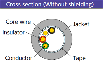
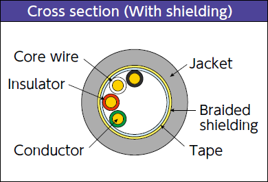
Cross section view (example)
Layer stranded type configuration diagram*4
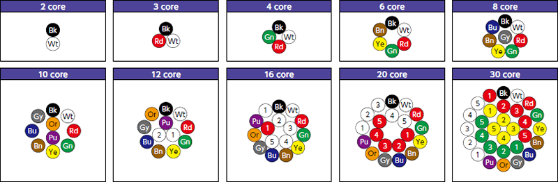
- *4 : The insulators from wire number 11 on bear dot marks, and the number inside the circle indicates the number of dot marks. For details, see Core wire identification and dot marks on page 33.
Lineup : Twisted pair type
Structure
| Conductor | Insulator | (2) Number of pairs |
Without shielding | With shielding | *7 Allowable electric current A (30††C) |
||||
|---|---|---|---|---|---|---|---|---|---|
| (1) AWG size |
sq. mm | Configuration wires/mm | *6 Outer diameter mm |
*6 Finished outer diameter mm |
Approximate weight kg/km | *6 Finished outer diameter mm |
Approximate weight kg/km | ||
| 26 | 0.14 | 7/0.16 | 0.98 | 2 | 5.1 | 25 | 5.5 | 43 | 2.6 |
| 3 | 5.8 | 31 | 6.2 | 54 | 2.2 | ||||
| 4 | 6.2 | 37 | 6.6 | 66 | 2.0 | ||||
| 5 | 6.6 | 43 | 7.0 | 68 | 1.8 | ||||
| 6 | 7.1 | 50 | 7.5 | 81 | 1.7 | ||||
| 7 | 7.1 | 53 | 7.5 | 79 | 1.6 | ||||
| 8 | 7.5 | 59 | 7.9 | 91 | 1.5 | ||||
| 10 | 8.0 | 70 | 8.4 | 100 | 1.4 | ||||
| 13 | 8.7 | 90 | 9.1 | 110 | 1.3 | ||||
| 15 | 9.2 | 100 | 9.6 | 120 | 1.2 | ||||
| 20 | 10.6 | 130 | 11.0 | 160 | 1.1 | ||||
| 25 | 11.3 | 160 | 11.8 | 180 | 1.0 | ||||
| 30 | 12.4 | 180 | 12.9 | 210 | 0.9 | ||||
| 34 | 12.9 | 200 | 13.4 | 230 | 0.9 | ||||
| 24 | 0.2 | 11/0.16 | 1.12 | 2 | 5.5 | 35 | 5.9 | 49 | 3.5 |
| 3 | 6.3 | 40 | 6.7 | 64 | 3.0 | ||||
| 4 | 6.8 | 48 | 7.2 | 68 | 2.7 | ||||
| 5 | 7.2 | 56 | 7.6 | 79 | 2.5 | ||||
| 6 | 7.7 | 66 | 8.1 | 93 | 2.3 | ||||
| 7 | 7.7 | 71 | 8.1 | 95 | 2.2 | ||||
| 8 | 8.3 | 81 | 8.7 | 115 | 2.1 | ||||
| 10 | 8.8 | 94 | 9.2 | 125 | 1.9 | ||||
| 13 | 9.7 | 120 | 10.2 | 140 | 1.7 | ||||
| 15 | 10.3 | 135 | 10.7 | 160 | 1.6 | ||||
| 20 | 11.8 | 170 | 12.2 | 200 | 1.5 | ||||
| 25 | 12.6 | 210 | 13.1 | 240 | 1.4 | ||||
| 30 | 13.8 | 240 | 14.3 | 280 | 1.3 | ||||
| 34 | 14.4 | 270 | 15.1 | 310 | 1.2 | ||||
| Conductor | Insulator | (2) Number of pairs |
Without shielding | With shielding | *7 Allowable electric current A (30††C) |
||||
|---|---|---|---|---|---|---|---|---|---|
| (1) AWG size |
sq. mm | Configuration wires/mm | *6 Outer diameter mm |
*6 Finished outer diameter mm |
Approximate weight kg/km | *6 Finished outer diameter mm |
Approximate weight kg/km | ||
| 22 | 0.3 | 17/0.16 | 1.29 | 2 | 6.1 | 37 | 6.5 | 61 | 4.6 |
| 3 | 6.9 | 49 | 7.3 | 75 | 4.0 | ||||
| 4 | 7.5 | 61 | 7.9 | 91 | 3.6 | ||||
| 5 | 7.9 | 70 | 8.3 | 105 | 3.3 | ||||
| 6 | 8.6 | 82 | 9.0 | 120 | 3.1 | ||||
| 7 | 8.6 | 90 | 9.0 | 125 | 2.9 | ||||
| 8 | 9.2 | 105 | 9.6 | 140 | 2.8 | ||||
| 10 | 9.8 | 125 | 10.3 | 160 | 2.6 | ||||
| 13 | 10.9 | 160 | 11.3 | 190 | 2.3 | ||||
| 15 | 11.5 | 180 | 11.9 | 210 | 2.2 | ||||
| 20 | 13.2 | 240 | 13.7 | 270 | 2.0 | ||||
| 25 | 14.2 | 280 | 14.9 | 320 | 1.8 | ||||
| 30 | 15.7 | 340 | 16.2 | 380 | 1.7 | ||||
| 34 | 16.4 | 380 | 16.9 | 420 | 1.6 | ||||
| 20 | 0.5 | 21/0.18 | 1.48 | 2 | 6.7 | 44 | 7.1 | 72 | 6.2 |
| 3 | 7.6 | 64 | 8.0 | 93 | 5.4 | ||||
| 4 | 8.3 | 79 | 8.7 | 115 | 4.8 | ||||
| 5 | 8.8 | 94 | 9.2 | 135 | 4.5 | ||||
| 6 | 9.5 | 110 | 9.9 | 155 | 4.2 | ||||
| 7 | 9.5 | 125 | 9.9 | 165 | 3.9 | ||||
| 8 | 10.4 | 140 | 10.8 | 190 | 3.8 | ||||
| 10 | 11.1 | 170 | 11.5 | 220 | 3.5 | ||||
| 13 | 12.2 | 220 | 12.7 | 250 | 3.1 | ||||
| 15 | 12.9 | 250 | 13.4 | 280 | 3.0 | ||||
| 20 | 14.9 | 320 | 15.6 | 370 | 2.7 | ||||
| 25 | 16.1 | 400 | 16.6 | 440 | 2.5 | ||||
| 30 | 17.7 | 470 | 18.2 | 510 | 2.3 | ||||
| 34 | 18.4 | 530 | 18.9 | 570 | 2.2 | ||||
- *6 : Insulator outer diameters and finished outer diameters are standard values.
- *7 : The allowable current is a calculated value for single-cable installation in the air and is not a guaranteed value.
Twisted pair type configuration diagram *8
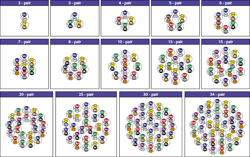
- *8 : The dotted circles indicate the pair configuration (twisted pairs) and the numbers indicate the pair numbers. The insulators from pair number 26 on bear dot marks.
For details, see Core wire identification and dot marks below.
Core wire identification and dot marks
Layer stranded type
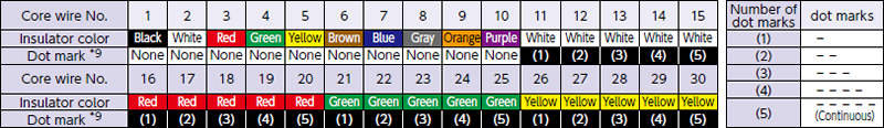
Twisted pair type
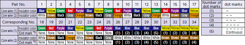
- *9 : The numbers inside brackets indicate dot marks (righthand table).
- Inquiries regarding materials, consultations, and technology
- Inquiry from Web: Inquiry form