- Home
- Products
- Electric Wire and Cable
- FA/Robot cable
- ORP cable series
FA/Robot cable
ORP cable series(UL 758 Style 2466 80°C 300V)

Overview
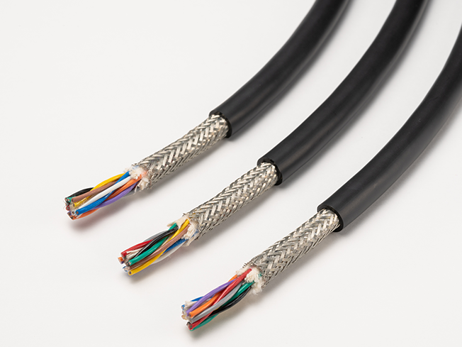
These cables are compatible with a rated voltage of 300 V.
They are suitable for moving parts that bend, slide, and twist.
Features
- Compatible with all robot movements (sliding, pivoting, and twisting), they can be used with a wide range of equipment types.
- They have excellent flexibility, which allows for improved routability.
Product code indication
Without shielding : ORP (1) SQ× (2) P
With shielding : ORP (1) SQ× (2) P(SB)
(1): Cross-sectional area of conductor(mm²) (2): Number of pairs (Please see the table below)
Specifications
Material and Structure
| conductor | Tin-plated, soft copper, twisting cable |
|---|---|
| insulator | Special elastomer |
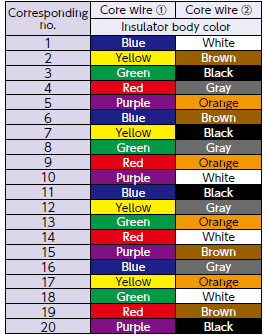
| Insulator identification | By (Table 1) |
| Shielding | Tin-plated, soft copper cable; braided |
| Jacket material (jacket color) | Oil-proof PVC (black matte) |
| Flame retardancy | VW-1 |
Usage environment
| Application | Fixed and moving parts between equipment and within equipment indoors |
|---|---|
| Operation temperature range |
-10 to 80°C |
Lineup
| Shielding | Twisted-pair types |
|---|---|
| Without shielding | Cross-sectional area of conductor: 0.2 to 0.5 mm² Number of pairs : 1 to 20 |
| With shielding | Cross-sectional area of conductor: 0.2 to 0.5 mm² Number of pairs : 1 to 20 |
Allowable bending radius
| Fixed part wiring | At least 4 times the cable outer diameter |
|---|---|
| Moving part wiring | At least 6 times the cable outer diameter (unshielded) |
| At least 8 times the cable outer diameter (shielded) |
Applicable standards
UL758 Style 2464 (Rating: 80˚C, 300 V)
Build-to-order manufacturing of UL listing (CL 3) standard-compliant products is available(. Cross-sectional area of conductor Excluding 0.2 mm²)
Jacket Marking

□ : Cross-sectional area of conductor (mm²) 0.2/0.3/0.5 △△ : Without shielding: No indication/With shielding: -SB
Special characteristics
Electrical performance
| Cross- sectional area of conductor mm² | AWG size |
Conductor resistance Ω /km (20°C) |
Insulator resistance MΩ -km (20°C) |
Withstand voltage V·1 minute interval |
|---|---|---|---|---|
| 0.2 | 25 | 105 or less | 100 or more | AC 2000 |
| 0.3 | 23 | 72 or less | ||
| 0.5 | 21 | 44 or less |
Movement performance
| Mode | Performance | Test conditions*1 |
|---|---|---|
| Sliding bending | 100 million times or more | Bend radius R: about 6 times the outer diameter of the cable Sliding speed: 70 times per minute Movement distance: 350 mm Count: one round trip is one count |
| Swinging bending | 20 million times or more | Bend radius R: about 8 times the outer diameter of the cable Bend angle: ±90° Bend speed: 40 times per minute Load: At least 4.9 N Count: one round trip is one count |
| Twisting | 20 million times or more | Twisting angle: ±180° Twisting speed: 70 times per minute Interval X: 500 mm Count: ±180°one round trip is one count |
- *1 : Under Oki test conditions and methods. For details, see page 4. These values are for reference only and are not guaranteed values.
Lineup : Twisted-pair types
Structure
| Conductor | Insulator | (2) Number of pairs |
Without shielding | With shielding | Allowable electric current A (30˚C)*3 |
||||
|---|---|---|---|---|---|---|---|---|---|
| (1) sq. mm |
AWG size |
Configuration wires/mm | Outer diameter mm *2 |
Outer diameter mm *2 |
Approximate weight kg/km |
Outer diameter mm *2 |
Approximate weight kg/km |
||
| 0.2 | 25 | 40/0.08 | 1.00 | 1 | 3.9 | 19 | 4.4 | 26 | 4.0 |
| 2 | 5.7 | 34 | 6.2 | 47 | 3.1 | ||||
| 3 | 6.2 | 43 | 6.7 | 56 | 2.7 | ||||
| 4 | 6.4 | 47 | 6.9 | 61 | 2.4 | ||||
| 5 | 7.2 | 59 | 7.7 | 77 | 2.2 | ||||
| 6 | 7.7 | 69 | 8.2 | 84 | 2.1 | ||||
| 8 | 8.8 | 90 | 9.3 | 110 | 1.9 | ||||
| 10 | 10.5 | 120 | 11.0 | 145 | 1.7 | ||||
| 15 | 11.0 | 145 | 11.5 | 170 | 1.5 | ||||
| 20 | 12.0 | 180 | 12.5 | 210 | 1.3 | ||||
| 0.3 | 23 | 60/0.08 | 1.25 | 1 | 4.4 | 24 | 4.9 | 34 | 5.5 |
| 2 | 6.6 | 45 | 7.1 | 60 | 4.2 | ||||
| 3 | 7.2 | 56 | 7.6 | 72 | 3.7 | ||||
| 4 | 7.9 | 71 | 8.4 | 89 | 3.3 | ||||
| 5 | 8.5 | 82 | 9.0 | 105 | 3.0 | ||||
| 6 | 9.3 | 98 | 9.8 | 125 | 2.8 | ||||
| 8 | 10.7 | 125 | 11.2 | 150 | 2.5 | ||||
| 10 | 12.2 | 155 | 12.7 | 185 | 2.3 | ||||
| 15 | 13.6 | 210 | 14.1 | 250 | 2.0 | ||||
| 20 | 15.2 | 260 | 15.7 | 300 | 1.8 | ||||
| 0.5 | 21 | 100/0.08 | 1.52 | 1 | 5.0 | 32 | 5.5 | 46 | 7.8 |
| 2 | 7.9 | 62 | 8.4 | 80 | 6.0 | ||||
| 3 | 8.5 | 84 | 9.0 | 110 | 5.2 | ||||
| 4 | 9.5 | 105 | 10.0 | 125 | 4.7 | ||||
| 5 | 10.6 | 125 | 11.1 | 150 | 4.3 | ||||
| 6 | 11.2 | 145 | 11.7 | 175 | 4.0 | ||||
| 8 | 13.4 | 195 | 13.9 | 230 | 3.6 | ||||
| 10 | 15.8 | 255 | 16.3 | 320 | 3.2 | ||||
| 15 | 16.7 | 320 | 17.2 | 360 | 2.9 | ||||
| 20 | 19.1 | 420 | 19.6 | 460 | 2.6 | ||||
- *2 : Insulator outer diameters and finished outer diameters are standard values.
- *3 : The allowable current is a calculated value for single-cable installation in the air and is not a guaranteed value.
(Tables 1)Identification of core wires(Twisted-pair types)
Twisted pair type configuration diagram*4
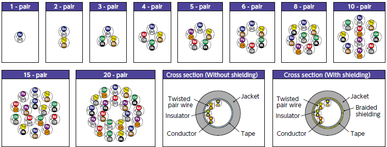
- *4 : The dotted circles indicate the pair configuration (twisted pairs) and the numbers indicate the pair numbers.
- Inquiries regarding materials, consultations, and technology
- Inquiry from Web: Inquiry form