- Home
- Products
- Electric Wire and Cable
- FA/Robot cable
- ORP-TW series
FA/Robot cable
ORP-TW series(UL 758 Style 2517 105°C 300V)

Overview
These cables are compatible with a rated voltage of 300 V.
They have been specialized for wiring to twisting moving parts.
Features
- We have achieved twisting durability of more than 50 million cycles (twistingdistance 500 mm).
- Resistant to localized twisting (even at a twisting distance of 100 mm, durability of more than 10 million cycles is ensured).
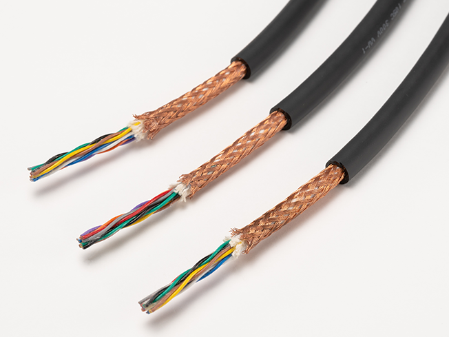
- This is a special shield that is difficult to break (using a special conductor with excellent flexibility and high tensile strength, the shield offers outstanding durability).
- Total lineup of 50 types (conductor sizes: 0.05 to 0.5 mm2, pair numbers: 3 to 8).
Product code indication
Without shielding : ORP-TW (1) SQ× (2) P(2517)
With shielding : ORP-TW (1) SQ× (2) P(SB)(2517)
(1): Cross-sectional area of conductor(mm2)
(2): Number of pairs (Please see the table below)
Specifications
Material and Structure
| conductor | Tin-plated, soft copper, twisting cable |
|---|---|
| insulator | Special elastomer |
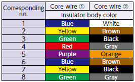
| Insulator identification | By (Table 1) |
| Shielding | Special braiding |
| Jacket material (jacket color) | Heat-/oil-resistant PVC (black matte) |
| Flame retardancy | VW-1 |
Usage environment
| Application | Fixed and moving parts between equipment and within equipment indoors |
|---|---|
| Operation temperature range |
-10 to 105°C |
Lineup
| Shielding | Twisted-pair types |
|---|---|
| Without shielding | Cross-sectional area of conductor: 0.05 to 0.5 mm2 Number of pairs : 3 to 8 |
| With shielding | Cross-sectional area of conductor: 0.05 to 0.5 mm2 Number of pairs : 3 to 8 |
Allowable bending radius
| Fixed part wiring | At least 4 times the cable outer diameter |
|---|---|
| Moving part wiring | At least 6 times the cable outer diameter (unshielded) |
| At least 8 times the cable outer diameter (shielded) |
Applicable standards
UL 758 Style 2517(Rating:105°C、300V)
Jacket Marking

□ : Cross-sectional area of conductor (mm2) 0.05/0.1/0.2/0.3/0.5 △△ : Without shielding: No indication/With shielding: -SB ####: Lot No.
Special characteristics
Electrical performance
| Cross- sectional area of conductor mm2 | AWG size |
Conductor resistance Ω /km (20°C) |
Insulator resistance MΩ -km (20°C) |
Withstand voltage V·1 minute interval |
|---|---|---|---|---|
| 0.05 | 30 | 340 or less | 100 or more | AC 2000 |
| 0.1 | 28 | 205 or less | ||
| 0.2 | 25 | 102 or less | ||
| 0.3 | 23 | 68 or less | ||
| 0.5 | 21 | 45 or less |
Movement performance
| Mode | Performance | Test conditions*1 |
|---|---|---|
| Sliding bending | 30 million times or more | Bend radius R: about 6 times the outer diameter of the cable Sliding speed: 70 times per minute Movement distance: 350 mm Count: one round trip is one count |
| Swinging bending | 3 million times or more | Bend radius R: about 8 times the outer diameter of the cable Bend angle: ±90° Bend speed: 40 times per minute Load: At least 4.9 N Count: one round trip is one count |
| Twisting | 50 million times or more (Spacing 500 mm) 10 million times or more (Spacing 100 mm) |
Twisting angle: ±180° Twisting speed: 90 times per minute Interval X: 500 mm Count: ±180°one round trip is one count |
- *1 : Under Oki test conditions and methods. For details, see page 4. These values are for reference only and are not guaranteed values.
Lineup : Twisted-pair types
Structure
| Conductor | Insulator | (2) Number of pairs |
Without shielding | With shielding | Allow able*3 electric current A (30˚C) |
||||
|---|---|---|---|---|---|---|---|---|---|
| (1) sq. mm |
AWG size |
Configura tion wires/mm |
Outer*2 dia meter mm |
Outer*2 dia meter mm |
Approx imate weight kg/km |
Outer*2 dia meter mm |
Approx imate weight kg/km |
||
| 0.05 | 30 | 30/0.05 | 0.66 | 3 | 4.9 | 25 | 5.6 | 34 | 1.4 |
| 4 | 5.3 | 29 | 6.0 | 38 | 1.2 | ||||
| 5 | 5.6 | 32 | 6.3 | 43 | 1.1 | ||||
| 6 | 6.0 | 36 | 6.6 | 48 | 1.1 | ||||
| 8 | 6.8 | 45 | 7.5 | 58 | 1.0 | ||||
| 0.1 | 28 | 49/0.05 | 0.74 | 3 | 5.8 | 32 | 5.1 | 25 | 1.9 |
| 4 | 5.6 | 33 | 6.3 | 44 | 1.7 | ||||
| 5 | 6.0 | 34 | 6.7 | 50 | 1.6 | ||||
| 6 | 6.4 | 43 | 7.1 | 55 | 1.5 | ||||
| 8 | 7.3 | 54 | 8.0 | 68 | 1.3 | ||||
| 0.2 | 25 | 102/0.05 | 0.93 | 3 | 5.9 | 37 | 6.6 | 47 | 3.1 |
| 4 | 6.5 | 47 | 7.2 | 59 | 2.8 | ||||
| 5 | 6.9 | 50 | 7.6 | 62 | 2.6 | ||||
| 6 | 7.4 | 63 | 8.1 | 76 | 2.4 | ||||
| 8 | 8.5 | 78 | 9.2 | 100 | 2.1 | ||||
| 0.3 | 23 | 108/0.06 | 1.09 | 3 | 6.3 | 47 | 7.0 | 58 | 4.1 |
| 4 | 7.1 | 60 | 7.8 | 73 | 3.7 | ||||
| 5 | 7.7 | 67 | 8.3 | 80 | 3.4 | ||||
| 6 | 8.2 | 80 | 8.9 | 95 | 3.2 | ||||
| 8 | 9.6 | 105 | 10.2 | 125 | 2.9 | ||||
| 0.5 | 21 | 177/0.06 | 1.36 | 3 | 7.2 | 67 | 7.9 | 81 | 5.9 |
| 4 | 7.9 | 83 | 8.6 | 97 | 5.3 | ||||
| 5 | 8.6 | 99 | 9.2 | 115 | 4.9 | ||||
| 6 | 9.2 | 115 | 9.9 | 135 | 4.6 | ||||
| 8 | 10.8 | 150 | 11.5 | 170 | 4.1 | ||||
- *2 : Insulator outer diameters and finished outer diameters are standard values.
- *3 : The allowable current is a calculated value for single-cable installation in the air and is not a guaranteed value.
(Tables 1)Identification of core wires(Twisted-pair types)
Twisted pair type configuration diagram*4
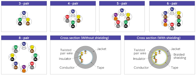
- *4 : The dotted circles indicate the pair configuration (twisted pairs) and the numbers indicate the pair numbers.
- Inquiries regarding materials, consultations, and technology
- Inquiry from Web: Inquiry form