- Home
- Products
- Electric Wire and Cable
- FA/Robot cable
- ORP-SL 105°C cable series
FA/Robot cable
ORP-SL 105°C cable series(UL 758 Style 2517 105°C 300V)

Overview
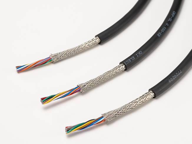
These cables have a rated voltage of 300 V and a smaller diameter compatible with smaller robots. They are suitable for moving parts that bend, slide, and twist.
Features
- While inheriting the features of the conventional ORP-SL, it complies with UL 758 Style 2517 (rated temperature: 105°C).
- These cables are designed for robot miniaturization, and their smaller diameter greatly improves routability in tight spaces.
- They support all robot movements (sliding, pivoting, and twisting) and can be used in a wide range of applications.
- They have excellent flexibility, which allows for improved routability.
Product code indication
ORP-SL 105C (1) SQ× (2) C(2517)
(1): Cross-sectional area of conductor(mm2) (2): Number of cores (Please see the table below)
Product code indication
Without shielding : ORP-SL 105C (1) SQ× (2) P(2517)
With shielding : ORP-SL 105C (1) SQ× (2) P(SB)(2517)
(1): Cross-sectional area of conductor(mm2) (2): Number of pairs (Please see the table below)
Specifications
Material and Structure
| conductor | Tin-plated, soft copper, twisting cable |
|---|---|
| insulator | Special elastomer |
| Insulator identification | From Tables 1 and 2 |
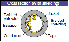
| Shielding | Tin-plated, soft copper cable; braided |
| Jacket material (jacket color) | Oil-proof PVC (black matte) |
| Flame retardancy | VW-1 |
Usage environment
| Application | Fixed and moving parts between equipment and within equipment indoors |
|---|---|
| Operation temperature range |
-10 to 80°C |
Lineup
| Shielding | Layer-stranded types | Twisted-pair types |
|---|---|---|
| Without shielding | Cross-sectional area of conductor: 0.05-0.5mm2 Number of cores: 3 to 15 |
Cross-sectional area of conductor: 0.05 to 0.5. mm2 Number of pairs : 1 to 20 |
| With shielding | - | Cross-sectional area of conductor: 0.05 to 0.5mm2 Number of pairs : 1 to 20 |
Allowable bending radius
| Fixed part wiring | At least 4 times the cable outer diameter |
|---|---|
| Moving part wiring | At least 6 times the cable outer diameter (unshielded) |
| At least 8 times the cable outer diameter (shielded) |
Applicable standards
UL 758 Style 2517 (Rating: 105°C, 300 V)
Build-to-order manufacturing of UL listing (CL 3) standard-compliant products is available.(Cross-sectional area of conductor 0.25mm2, 0.3mm2, 0.5 mm2 only)
Jacket Marking

□ : Cross-sectional area of conductor(mm2) 0.05/0.1/0.15/0.2/0.25/0.3/0.5
△△ : Without shielding: No indication/With shielding: -SB ####: Lot No.
Special characteristics
Electrical performance
| Cross- sectional area of conductor mm2 | AWG size |
Conductor resistance Ω /km (20°C) |
Insulator resistance MΩ -km (20°C) |
Withstand voltage V·1 minute interval |
|---|---|---|---|---|
| 0.05 | 30 | 340 or less | 100 or more | AC 2000 |
| 0.1 | 28 | 205 or less | ||
| 0.15 | 26 | 130 or less | ||
| 0.2 | 25 | 102 or less | ||
| 0.25 | 24 | 80 or less | ||
| 0.3 | 23 | 66 or less | ||
| 0.5 | 21 | 45 or less |
Movement performance
| Mode | Performance | Test conditions*1 |
|---|---|---|
| Sliding bending | 100 million times or more | Bend radius R: about 6 times the outer diameter of the cable Sliding speed: 70 times per minute Movement distance: 350 mm Count: one round trip is one count |
| Swinging bending | 20 million times or more | Bend radius R: about 8 times the outer diameter of the cable Bend angle: ±90° Bend speed: 40 times per minute Load: At least 4.9 N Count: one round trip is one count |
| Twisting | 20 million times or more | Twisting angle: ±180° Twisting speed: 70 times per minute Interval X: 500 mm Count: ±180°one round trip is one count |
- *1 : Under Oki test conditions and methods. For details, see page 4. These values are for reference only and are not guaranteed values.
Lineup : Layer-stranded types
Structure
| Conductor | Insulator | (2) Number of cores |
Without shielding | Allowable electric current A (30˚C)*3 | |||
|---|---|---|---|---|---|---|---|
| (1) sq. mm |
AWG size |
Configuration wires/mm |
Outer diameter mm*2 | Outer diameter mm*2 |
Approximate weight kg/km | ||
| 0.05 | 30 | 30/0.05 | 0.66 | 3 | 3.4 | 12.8 | 1.8 |
| 4 | 3.6 | 14.6 | 1.6 | ||||
| 5 | 3.7 | 15.9 | 1.5 | ||||
| 6 | 3.9 | 17.7 | 1.4 | ||||
| 7 | 4.0 | 19.0 | 1.3 | ||||
| 8 | 4.1 | 20.4 | 1.2 | ||||
| 10 | 4.6 | 24.3 | 1.1 | ||||
| 15 | 5.0 | 32.3 | 1.0 | ||||
| 0.1 | 28 | 49/0.05 | 0.74 | 3 | 3.6 | 14.9 | 2.4 |
| 4 | 3.8 | 17.1 | 2.2 | ||||
| 5 | 4.0 | 19.0 | 2.0 | ||||
| 6 | 4.2 | 21.1 | 1.9 | ||||
| 7 | 4.3 | 23.1 | 1.8 | ||||
| 8 | 4.4 | 24.8 | 1.7 | ||||
| 10 | 4.8 | 29.1 | 1.6 | ||||
| 15 | 5.4 | 40.3 | 1.3 | ||||
| 0.15 | 26 | 78/0.05 | 0.85 | 3 | 3.8 | 17.6 | 3.3 |
| 4 | 4.2 | 20.4 | 3.0 | ||||
| 5 | 4.2 | 22.9 | 2.8 | ||||
| 6 | 4.4 | 26.0 | 2.6 | ||||
| 7 | 4.5 | 28.3 | 2.4 | ||||
| 8 | 4.7 | 31.1 | 2.3 | ||||
| 10 | 5.4 | 38.2 | 2.1 | ||||
| 15 | 5.8 | 49.9 | 1.8 | ||||
| 0.2 | 25 | 102/0.05 | 0.93 | 3 | 4.0 | 19.7 | 4.0 |
| 4 | 4.2 | 22.9 | 3.6 | ||||
| 5 | 4.5 | 26.8 | 3.3 | ||||
| 6 | 4.8 | 30.6 | 3.1 | ||||
| 7 | 4.9 | 33.7 | 2.9 | ||||
| 8 | 5.1 | 37.0 | 2.8 | ||||
| 10 | 5.5 | 43.2 | 2.5 | ||||
| 15 | 6.2 | 59.2 | 2.2 | ||||
| 0.25 | 24 | 87/0.06 | 0.99 | 3 | 4.1 | 21.2 | 4.6 |
| 4 | 4.4 | 26.7 | 4.1 | ||||
| 5 | 4.6 | 29.5 | 3.8 | ||||
| 6 | 4.9 | 34.1 | 3.5 | ||||
| 7 | 5.0 | 37.3 | 3.3 | ||||
| 8 | 5.2 | 41.0 | 3.2 | ||||
| 10 | 5.6 | 48.8 | 2.9 | ||||
| 15 | 6.5 | 68.1 | 2.5 | ||||
| 0.3 | 23 | 108/0.06 | 1.09 | 3 | 4.3 | 24.2 | 5.3 |
| 4 | 4.6 | 29.0 | 4.8 | ||||
| 5 | 4.9 | 34.0 | 4.4 | ||||
| 6 | 5.3 | 39.4 | 4.1 | ||||
| 7 | 5.4 | 43.5 | 3.9 | ||||
| 8 | 5.6 | 47.7 | 3.7 | ||||
| 10 | 6.1 | 57.3 | 3.4 | ||||
| 15 | 6.9 | 79.2 | 2.9 | ||||
| 0.5 | 21 | 177/0.06 | 1.36 | 3 | 4.8 | 32.6 | 7.6 |
| 4 | 5.2 | 39.9 | 6.8 | ||||
| 5 | 5.6 | 48.6 | 6.3 | ||||
| 6 | 6.0 | 56.6 | 5.9 | ||||
| 7 | 6.1 | 62.2 | 5.5 | ||||
| 8 | 6.4 | 69.3 | 5.3 | ||||
| 10 | 7.1 | 84.3 | 4.9 | ||||
| 15 | 8.1 | 121.4 | 4.2 | ||||
- *2 : Insulator outer diameters and finished outer diameters are standard values.
- *3 : The allowable current is a calculated value for single-cable installation in the air and is not a guaranteed value.
Layer stranded type configuration diagram
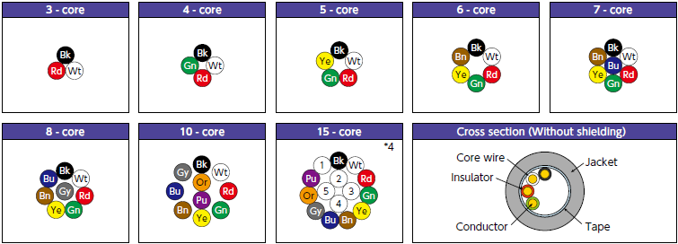
- *4 : The numbers inside circles indicate dot marks. For details, see Core wire identification and dot marks on page 11.
Lineup : Twisted-pair types
Structure
| Conductor | Insulator | (2) Number of cores |
Without shielding | With shielding | Allowable electric current* A (30˚C)*7 | ||||
|---|---|---|---|---|---|---|---|---|---|
| (1) sq. mm |
AWG size |
Configuration wires/mm | Outer diameter mm*6 | Outer diameter mm*6 | Approximate weight kg/km | Oute*r6 diameter mm | Approximate weight kg/km | ||
| 0.05 | 30 | 30/0.05 | 0.66 | 1 | 3.2 | 10.8 | 3.5 | 15.6 | 2.1 |
| 2 | 3.8 | 15.7 | 4.1 | 21.9 | 1.6 | ||||
| 3 | 4.1 | 18.3 | 4.4 | 24.9 | 1.4 | ||||
| 4 | 4.7 | 23.0 | 5.0 | 31.2 | 1.2 | ||||
| 5 | 5.0 | 26.3 | 5.3 | 34.7 | 1.1 | ||||
| 6 | 5.3 | 29.4 | 5.6 | 38.4 | 1.1 | ||||
| 7 | 5.4 | 31.2 | 5.7 | 40.4 | 1.0 | ||||
| 8 | 5.8 | 35.2 | 6.1 | 45.9 | 0.9 | ||||
| 10 | 6.2 | 41.2 | 6.5 | 52.4 | 0.9 | ||||
| 13 | 6.7 | 49.7 | 7.0 | 62.6 | 0.8 | ||||
| 15 | 7.0 | 54.9 | 7.3 | 68.6 | 0.8 | ||||
| 20 | 7.5 | 66.9 | 7.8 | 81.5 | 0.7 | ||||
| 0.1 | 28 | 49/0.05 | 0.74 | 1 | 3.3 | 12.0 | 3.8 | 19.7 | 2.8 |
| 2 | 4.4 | 21.4 | 4.8 | 31.4 | 2.2 | ||||
| 3 | 4.7 | 25.0 | 5.1 | 35.4 | 1.9 | ||||
| 4 | 5.0 | 27.6 | 5.4 | 38.1 | 1.7 | ||||
| 5 | 5.3 | 31.3 | 5.7 | 41.9 | 1.6 | ||||
| 6 | 5.6 | 35.8 | 6.0 | 47.1 | 1.4 | ||||
| 7 | 5.6 | 37.8 | 6.0 | 49.1 | 1.4 | ||||
| 8 | 6.0 | 42.5 | 6.4 | 56.8 | 1.3 | ||||
| 10 | 6.6 | 52.4 | 7.0 | 65.0 | 1.2 | ||||
| 13 | 7.3 | 65.2 | 7.7 | 82.3 | 1.1 | ||||
| 15 | 7.6 | 68.4 | 8.0 | 86.1 | 1.0 | ||||
| 20 | 8.6 | 87.5 | 9.0 | 106 | 0.9 | ||||
| 0.15 | 26 | 78/0.05 | 0.85 | 1 | 3.6 | 14.4 | 4.0 | 21.8 | 3.8 |
| 2 | 4.4 | 22.6 | 4.8 | 32.3 | 3.0 | ||||
| 3 | 4.9 | 29.3 | 5.3 | 39.3 | 2.6 | ||||
| 4 | 5.4 | 34.5 | 5.8 | 46.9 | 2.3 | ||||
| 5 | 5.8 | 39.9 | 6.2 | 52.9 | 2.1 | ||||
| 6 | 6.2 | 46.3 | 6.6 | 60.3 | 2.0 | ||||
| 7 | 6.3 | 49.6 | 6.7 | 63.9 | 1.9 | ||||
| 8 | 6.6 | 55.6 | 7.0 | 70.6 | 1.8 | ||||
| 10 | 7.3 | 67.6 | 7.7 | 83.6 | 1.7 | ||||
| 13 | 8.4 | 83.0 | 8.8 | 103.1 | 1.5 | ||||
| 15 | 9.1 | 98.4 | 9.5 | 119.7 | 1.4 | ||||
| 20 | 9.6 | 122.7 | 10.0 | 145.2 | 1.3 | ||||
| 0.2 | 25 | 102/0.05 | 0.93 | 1 | 3.7 | 16.2 | 4.2 | 23.6 | 4.6 |
| 2 | 5.0 | 29.3 | 5.4 | 39.8 | 3.6 | ||||
| 3 | 5.3 | 34.2 | 5.7 | 45.0 | 3.1 | ||||
| 4 | 5.7 | 40.0 | 6.3 | 55.1 | 2.8 | ||||
| 5 | 6.1 | 46.2 | 6.5 | 59.8 | 2.5 | ||||
| 6 | 6.6 | 54.3 | 7.1 | 68.8 | 2.4 | ||||
| 7 | 6.7 | 58.2 | 7.2 | 72.7 | 2.2 | ||||
| 8 | 7.1 | 65.8 | 7.6 | 81.3 | 2.1 | ||||
| 10 | 7.8 | 79.3 | 8.2 | 97.2 | 2.0 | ||||
| 13 | 9.3 | 108.8 | 9.7 | 125.9 | 1.8 | ||||
| 15 | 9.6 | 119.3 | 10.0 | 148.4 | 1.7 | ||||
| 20 | 10.2 | 150.0 | 10.6 | 180.8 | 1.5 | ||||
| 0.25 | 24 | 87/0.06 | 0.99 | 1 | 3.9 | 17.6 | 4.3 | 25.3 | 5.2 |
| 2 | 5.1 | 30.3 | 5.5 | 39.0 | 4.1 | ||||
| 3 | 5.5 | 38.4 | 5.9 | 48.6 | 3.5 | ||||
| 4 | 5.9 | 45.7 | 6.3 | 56.2 | 3.2 | ||||
| 5 | 6.3 | 52.5 | 6.7 | 65.7 | 2.9 | ||||
| 6 | 6.8 | 61.5 | 7.2 | 77.1 | 2.7 | ||||
| 7 | 6.9 | 66.1 | 7.3 | 81.8 | 2.6 | ||||
| 8 | 7.4 | 75.3 | 7.8 | 91.4 | 2.4 | ||||
| 10 | 8.2 | 92.6 | 8.6 | 111.7 | 2.3 | ||||
| 13 | 9.5 | 119.5 | 9.9 | 140.6 | 2.1 | ||||
| 15 | 10.0 | 133.9 | 10.0 | 156.2 | 1.9 | ||||
| 20 | 10.6 | 169.7 | 11.0 | 193.9 | 1.7 | ||||
| 0.3 | 23 | 108/0.06 | 1.09 | 1 | 4.0 | 19.2 | 4.4 | 26.6 | 6.1 |
| 2 | 5.5 | 35.1 | 5.9 | 47.1 | 4.8 | ||||
| 3 | 5.9 | 43.9 | 6.4 | 56.5 | 4.1 | ||||
| 4 | 6.3 | 52.1 | 6.7 | 64.7 | 3.7 | ||||
| 5 | 6.9 | 62.1 | 7.3 | 76.6 | 3.4 | ||||
| 6 | 7.4 | 72.8 | 7.8 | 88.8 | 3.2 | ||||
| 7 | 7.4 | 77.0 | 7.8 | 93.0 | 3.0 | ||||
| 8 | 8.0 | 89.0 | 8.4 | 106.1 | 2.8 | ||||
| 10 | 8.8 | 108.6 | 9.2 | 120.5 | 2.7 | ||||
| 13 | 10.4 | 144.5 | 10.8 | 164.1 | 2.4 | ||||
| 15 | 10.6 | 163.0 | 11.0 | 191.6 | 2.3 | ||||
| 20 | 12.0 | 203.6 | 12.1 | 258.1 | 2.0 | ||||
| 0.5 | 21 | 177/0.06 | 1.36 | 1 | 4.6 | 25.7 | 5.0 | 36.7 | 8.7 |
| 2 | 6.4 | 50.6 | 6.8 | 66.7 | 6.8 | ||||
| 3 | 6.9 | 63.8 | 7.3 | 81.9 | 5.9 | ||||
| 4 | 7.5 | 75.1 | 7.9 | 93.8 | 5.3 | ||||
| 5 | 7.8 | 88.9 | 8.2 | 107.2 | 4.9 | ||||
| 6 | 9.0 | 111.9 | 9.4 | 133 | 4.5 | ||||
| 7 | 9.1 | 120.9 | 9.5 | 142.2 | 4.3 | ||||
| 8 | 9.7 | 138.1 | 10.1 | 161.1 | 4.1 | ||||
| 10 | 11.4 | 175.1 | 11.8 | 202.4 | 3.8 | ||||
| 13 | 12.4 | 210.3 | 12.3 | 240.5 | 3.5 | ||||
| 15 | 12.6 | 236.8 | 13.0 | 267.5 | 3.3 | ||||
| 20 | 14.1 | 308.0 | 14.5 | 342.6 | 2.9 | ||||
- *6 : Insulator outer diameters and finished outer diameters are standard values.
- *7 : The allowable current is a calculated value for single-cable installation in the air and is not a guaranteed value.
Twisted pair type configuration diagram *8
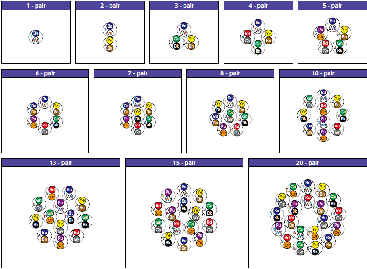
- *8 : The dotted circles indicate the pair configuration (twisted pairs) and the numbers indicate the pair numbers.
(Tables 1)Core wire identification(Layer-stranded types)
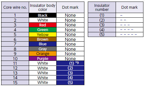
- *9 : The numbers inside brackets indicate dot marks (righthand table).
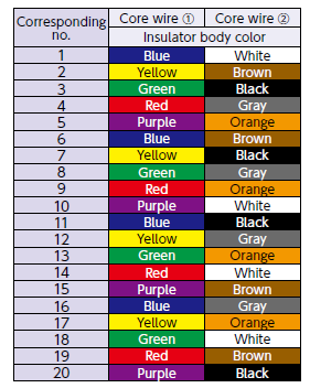
(Tables 2)Core wire identification(Twisted-pair types)
- Inquiries regarding materials, consultations, and technology
- Inquiry from Web: Inquiry form