- Home
- Products
- Electric Wire and Cable
- FA/Robot cable
- ORP-I series
FA/Robot cable
ORP-I series(UL 758 Style 11502 105°C 600V)

Overview
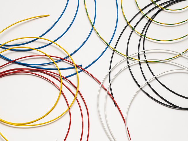
These are insulated wires compatible with a rated voltage of 600 V and use a special elastomer as the insulator. They are suitable for wiring to moving parts inside equipment.
Features
- The diameters are smaller than cables, giving them smaller bending radiuses and making them ideal for wiring in tight spaces.
- Adopting our proprietary special elastomer insulation, ORP-I inherits both the excellent movability and the low cost of the ORP series.
- Compatible with 600 V rating in spite of its small diameter.
- We also provide customization services such as pair twisting, spiral forming, connector fitting, etc. to meet your needs.
Product code indication
ORP-I (1) SQ(11502)(2)
(1): Cross-sectional area of conductor: 0.05 to 0.5mm²
(2): Insulator color symbol Red:R、Black:K、Blue:B、White:W、Yellow:Y、Green:G、Yellow/green spiral marks付:Y/G*1
- *1 : Yellow/green spiral marks are for conductor sizes of 0.2 mm² (25 AWG) or larger.
Specifications
Material and Structure
| conductor | Tin-plated, soft copper, twisting cable |
|---|---|
| insulator | Special elastomer |
| Insulator identification | Insulator body color |
| Applicable standards/ratings | UL 758 Style 11502 105°C、600V |
| Flame retardancy | Horizontal burning |
| Application | Fixed and moving parts indoor and inside devices |
| Operation temperature range | -10 to 105°C |
Movement performance
| Mode | Performance | Test conditions*2 |
|---|---|---|
| Swinging bending | 10 million times or more | Bend radius R: about 15 times the outer diameter of the cable Bend angle: ±90° Bend speed: 40 times per minute Load: At least 1.0 N Count: one round trip is one count |
- *2 : Under Oki test conditions and methods. For details, see page 4. These values are for reference only and are not guaranteed values.
Allowable bending radius
| Fixed part wiring | At least 4 times the outer diameter of the insulator |
|---|---|
| Moving part wiring | At least 15 times the outer diameter of the insulator |
Lineup
Structure
| Cross-sectional area of conductor mm² | AWG size | Configuration wires/mm | Outer diameter of conductor mm | Insulator outer diameters mm*3 | Standard length: m | Approximate weight kg/km | Minimun bending radius mm | Allowable electric current A (30˚C)*4 | Conductor resistance Ω /km(20°C) | Insulator resistance MΩ -km(20°C) | Withstand voltage V·1 minute interval |
|---|---|---|---|---|---|---|---|---|---|---|---|
| 0.05 | 30 | 30/0.05 | 0.32 | 0.74 | 100 | 1.0 | 5 | 2.8 | 340 or less | 100 or more | AC2000 |
| 0.1 | 28 | 49/0.05 | 0.40 | 0.82 | 1.5 | 3.8 | 205 or less | ||||
| 0.15 | 26 | 78/0.05 | 0.51 | 0.93 | 2.0 | 6 | 5.1 | 130 or less | |||
| 0.2 | 25 | 40/0.08 | 0.58 | 1.00 | 3.0 | 6.3 | 98 or less | ||||
| 0.3 | 23 | 60/0.08 | 0.75 | 1.25 | 4.0 | 8 | 8.4 | 66 or less | |||
| 0.5 | 21 | 100/0.08 | 0.92 | 1.52 | 7.0 | 9 | 12.0 | 40 or less | |||
| 0.75 | 19 | 150/0.08 | 1.13 | 1.73 | 9.0 | 11 | 15.5 | 26 or less | |||
| 1.25 | 17 | 7/36/0.08 | 1.50 | 2.20 | 15.0 | 13 | 22.5 | 16 or less | |||
| 2 | 15 | 7/57/0.08 | 1.90 | 2.60 | 22.0 | 16 | 30.5 | 9.3 or less | |||
| 3.5 | 12 | 7/64/0.1 | 2.60 | 3.40 | 38.0 | 21 | 46.0 | 5.7 or less | |||
| 5.5 | 10 | 7/100/0.1 | 3.35 | 4.15 | 58.0 | 25 | 63.3 | 3.6 or less |
- *3 : Insulator outer diameters are standard values.
- *4 : The allowable current is a value calculated based on midair single-cable wiring at ambient temperature of 30˚C, not a guaranteed value.
When binding electrical wires, calculate the value using the following formula: Allowable current value when bound (30˚C) = Allowable current value per wire (30˚C) × (the number of bound wires)Äsl142Äslmult0 -0.3623
- Inquiries regarding materials, consultations, and technology
- Inquiry from Web: Inquiry form