- Home
- Products
- Electric Wire and Cable
- FA/Robot cable
- ORP-D cable series
FA/Robot cable
ORP-D cable series(UL 758 Style 2586 105°C 600V)

Overview
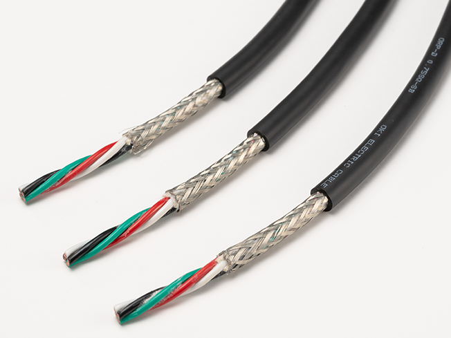
These power cables for moving parts are compatible with a rated voltage of 600 V. The diameter has been successfully reduced to match that of 300 V rated products, improving ease of installation.
Features
- Our proprietary special elastomer insulation is used to achieve both excellent movability and low cost.
- While compatible with a 600 V rating, the diameter has been reduced to match that of a 300 V rating.
It has achieved compatibility with ordinary 300 V rated cables. - Its excellent flexibility and ease of handling make it ideal for small devices where mounting space is limited and wiring is difficult.
Product code indication
Without shielding : ORP-D (1) SQ × (2) C (2586)
With shielding : ORP-D (1) SQ × (2) C (SB) (2586)
(1): Cross-sectional area of conductor(mm2) (2): Number of cores (Please see the table below)
Specifications
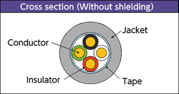
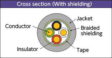
Material and Structure
| conductor | Tin-plated, soft copper, twisting cable |
|---|---|
| insulator | Special elastomer |
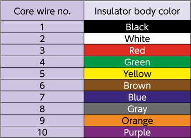
| Insulator identification | By (Table 1) |
| Shielding | Tin-plated, soft copper cable; braided |
| Jacket material (jacket color) | Heat-/oil-resistant PVC (black matte) |
| Flame retardancy | VW-1 |
Usage environment
| Application | Fixed and moving parts between equipment and within equipment indoors |
|---|---|
| Operation temperature range |
-10 to 105°C |
Lineup
| Shielding | Layer-stranded types |
|---|---|
| Without shielding | Cross-sectional area of conductor: 0.5-5.5mm² Number of cores: 2 to 10 |
| With shielding | Cross-sectional area of conductor: 0.5-5.5mm² Number of cores: 2 to 10 |
Allowable bending radius
| Fixed part wiring | At least 4 times the cable outer diameter |
|---|---|
| Moving part wiring | At least 6 times the cable outer diameter (unshielded) |
| At least 8 times the cable outer diameter (shielded) |
Applicable standards
UL758 Style 2586 (Rating: 105˚C, 600 V)
Build-to-order manufacturing of UL listing (CL 3) standard-compliant products is available.(Cross-sectional area of conductor Excluding 5.5 mm²)
Jacket Marking

□ : Cross-sectional area of conductor(mm²) 0.5/0.75/1.25/2/3.5/5.5
△△ : Without shielding: No indication/With shielding: -SB ####: Lot No.
Special characteristics
Electrical performance
| Conductor cross- sectional area mm² | AWG size |
Conductor resistance Ω /km (20°C) |
Insulator resistance MΩ -km (20°C) |
Withstand voltage V·1 minute interval |
|---|---|---|---|---|
| 0.5 | 21 | 40 or less | 100 or more | AC 2000 |
| 0.75 | 19 | 26 or less | ||
| 1.25 | 17 | 16 or less | ||
| 2 | 15 | 9.3 or less | ||
| 3.5 | 12 | 5.3 or less | ||
| 5.5 | 10 | 3.4 or less |
Movement performance
| Mode | Performance | Test conditions*1 |
|---|---|---|
| Sliding bending | 100 million times or more |
Bend radius R: about 6 times the outer diameter of the cable Sliding speed: 70 times per minute Movement distance: 350 mm Count: one round trip is one count |
| Swinging bending | 20 million times or more |
Bend radius R: about 8 times the outer diameter of the cable Bend angle: ±90° Bend speed: 40 times per minute Load: At least 4.9 N Count: one round trip is one count |
| Twisting | 20 million times or more |
Twisting angle: ±180° Twisting speed: 70 times per minute Interval X: 500 mm Count: ±180° one round trip is one count |
- *1 : Under Oki test conditions and methods. For details, see page 4. These values are for reference only and are not guaranteed values.
Lineup : Layer-stranded types
Structure
| Conductor | Insulator | (2) Number of cores |
Without shielding | With shielding | *3 Allowable electric current A (30˚C) |
||||
|---|---|---|---|---|---|---|---|---|---|
| (1) sq. mm |
AWG size |
Configuration wires/mm |
Outer*2 diameter mm |
Outer*2 diameter mm |
Approximate weight kg/km |
Outer*2 diameter mm |
Approximate weight kg/km |
||
| 0.5 | 21 | 100/0.08 | 1.52 | 2 | 5.3 | 34 | 5.7 | 45 | 9.2 |
| 3 | 5.5 | 41 | 5.9 | 53 | 7.9 | ||||
| 4 | 5.9 | 49 | 6.3 | 61 | 7.1 | ||||
| 5 | 6.3 | 58 | 6.7 | 72 | 6.6 | ||||
| 6 | 6.8 | 66 | 7.2 | 83 | 6.1 | ||||
| 8 | 8.0 | 90 | 8.4 | 110 | 5.5 | ||||
| 10 | 8.9 | 110 | 9.3 | 130 | 5.1 | ||||
| 0.75 | 19 | 150/0.08 | 1.73 | 2 | 5.7 | 41 | 6.1 | 53 | 12.2 |
| 3 | 5.9 | 51 | 6.3 | 62 | 10.5 | ||||
| 4 | 6.4 | 63 | 6.8 | 75 | 9.4 | ||||
| 5 | 6.9 | 74 | 7.3 | 88 | 8.7 | ||||
| 6 | 7.4 | 87 | 7.8 | 105 | 8.2 | ||||
| 8 | 8.8 | 120 | 9.3 | 145 | 7.3 | ||||
| 10 | 9.7 | 145 | 10.3 | 175 | 6.8 | ||||
| 1.25 | 17 | 7/36/0.08 | 2.2 | 2 | 6.6 | 58 | 7.0 | 72 | 17.3 |
| 3 | 7.0 | 75 | 7.4 | 89 | 14.9 | ||||
| 4 | 7.5 | 92 | 7.9 | 110 | 13.4 | ||||
| 5 | 8.1 | 110 | 8.7 | 135 | 12.4 | ||||
| 6 | 8.8 | 130 | 9.3 | 155 | 11.6 | ||||
| 8 | 10.5 | 180 | 11.1 | 210 | 10.4 | ||||
| 10 | 11.6 | 215 | 12.1 | 250 | 9.6 | ||||
| 2 | 15 | 7/57/0.08 | 2.6 | 2 | 7.4 | 79 | 7.8 | 94 | 23.6 |
| 3 | 7.8 | 105 | 8.2 | 120 | 20.3 | ||||
| 4 | 8.5 | 130 | 9.0 | 155 | 18.3 | ||||
| 5 | 9.2 | 155 | 9.7 | 185 | 16.9 | ||||
| 6 | 10.0 | 185 | 10.5 | 215 | 15.8 | ||||
| 8 | 12.0 | 250 | 12.5 | 285 | 14.2 | ||||
| 10 | 13.2 | 305 | 13.7 | 350 | 13.1 | ||||
| 3.5 | 12 | 7/64/0.10 | 3.4 | 2 | 9.1 | 125 | 9.5 | 150 | 35.8 |
| 3 | 9.6 | 165 | 10.3 | 195 | 30.9 | ||||
| 4 | 10.5 | 210 | 11.2 | 240 | 27.8 | ||||
| 5 | 11.7 | 265 | 12.4 | 275 | 25.7 | ||||
| 6 | 12.7 | 290 | 13.4 | 325 | 24.0 | ||||
| 8 | 15.1 | 425 | 16.0 | 470 | 21.6 | ||||
| 10 | 16.9 | 505 | 17.4 | 560 | 19.9 | ||||
| 5.5 | 10 | 7/100/0.10 | 4.15 | 2 | 11.2 | 190 | 11.7 | 220 | 48.9 |
| 3 | 11.8 | 250 | 12.3 | 275 | 42.2 | ||||
| 4 | 12.9 | 290 | 13.4 | 320 | 38.0 | ||||
| 5 | 14.3 | 390 | 14.8 | 430 | 35.0 | ||||
| 6 | 15.5 | 465 | 16.0 | 510 | 32.8 | ||||
| 8 | 18.6 | 620 | 19.1 | 670 | 29.6 | ||||
| 10 | 20.5 | 755 | 21.0 | 815 | 27.3 | ||||
- *2 : Insulator outer diameters and finished outer diameters are standard values.
- *3 : The allowable current is a calculated value for single-cable installation in the air and is not a guaranteed value.
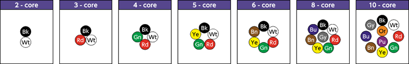
(Tables 1)Identification of core wires(layer-stranded types)
Layer stranded type configuration diagram
- Inquiries regarding materials, consultations, and technology
- Inquiry from Web: Inquiry form