- Home
- Products
- Electric Wire and Cable
- FA/Robot cable
- ORP-30F cable series
FA/Robot cable
ORP-30F cable series(UL 758 Style 21103 105°C 30V)

Overview
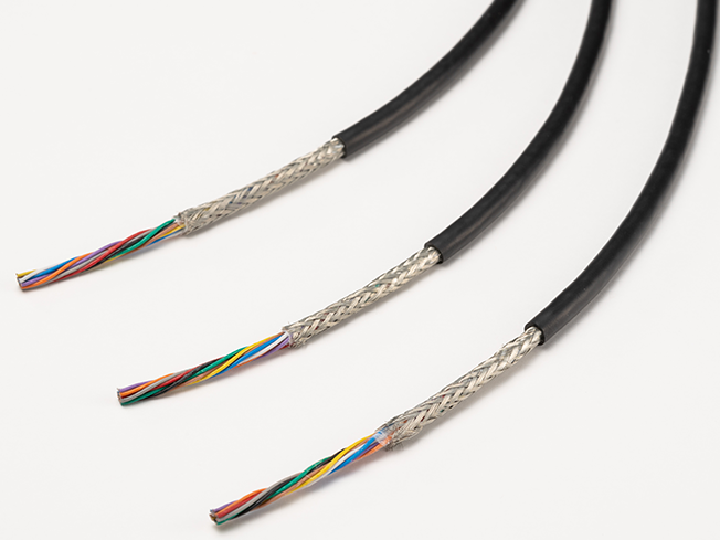
With a rated voltage of 30 V, these cables are specialized for wiring inside equipment. The smaller diameter makes them suitable for wiring to moving parts in tight spaces, etc.
Features
- The diameter has been successfully reduced by up to 32%, compared to our conventional products.
- Excellent movement durability has been achieved through the use of special elastomers.
- The cables use a heat- and oil-resistant reinforced PVC jacket, designed to withstand harsh operating environments.
- Extensive product lineup (224 types in all)
Conductor sizes: The lineup includes 34 to 22 AWG, layer-stranded types, twisted pair types, with or without shielding
Product code indication
Without shielding : ORP-30F (1) AWG× (2) P (21103)
With shielding : ORP-30F (1)AWG× (2) P (SB) (21103)
(1): Conductor AWG size (2): Number of cores (Please see the table below)
Without shielding : ORP-30F (1) AWG× (2) C (21103)
With shielding : ORP-30F (1) AWG× (2) C (SB) (21103)
(1): Conductor AWG size (2): Number of cores (Please see the table below)
Specifications
Material and Structure
| conductor | Tin-plated, soft copper, twisting cable |
|---|---|
| insulator | Special elastomer |
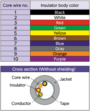
| Insulator identification | From Tables 1 and 2 |
| Shielding | Tin-plated, soft copper cable; braided |
| Jacket material (jacket color) | Heat- and oil-resistant reinforced PVC (black matte) |
| Flame retardancy | Horizontal burning |
Usage environment
| Application | Fixed/moving parts inside equipment |
|---|---|
| Operation temperature range |
-10 to 105°C |
Lineup
| Shielding | Layer-stranded types | Twisted-pair types |
|---|---|---|
| Without shielding | Conductor size : 34 to 22AWG Number of cores: 2 to 10 |
Conductor size : 34 to 22AWG Number of pairs : 2 to 10 |
| With shielding | Conductor size : 34 to 22AWG Number of cores: 2 to 10 |
Conductor size : 34 to 22AWG Number of pairs : 2 to 20*1 |
- *1 : 20-pair cables only available with 24 AWG and shielding.
Allowable bending radius
| Fixed part wiring | At least 4 times the cable outer diameter |
|---|---|
| Moving part wiring | At least 6 times the cable outer diameter (unshielded) |
| At least 8 times the cable outer diameter (shielded) |
Applicable standards
UL 758 Style 21103 (Rating: 105°C, 30 V)
Jacket Marking

□ : Conductor size (AWG) 34/32/30/28/26/24/22
△△ : Without shielding: No indication/With shielding: -SB ####: Lot No.
Special characteristics
Electrical performance
| Cross- sectional area of conductor mm2 | AWG size |
Conductor resistance Ω /km (20°C) |
Insulator resistance MΩ -km (20°C) |
Withstand voltage V·1 minute interval |
|---|---|---|---|---|
| 0.02 | 34 | 860 or less | 100 or more | AC 500 |
| 0.04 | 32 | 550 or less | ||
| 0.05 | 30 | 340 or less | ||
| 0.1 | 28 | 205 or less | ||
| 0.15 | 26 | 130 or less | ||
| 0.25 | 24 | 80 or less | ||
| 0.35 | 22 | 61 or less |
Movement performance
| Mode | Performance | Test conditions*2 |
|---|---|---|
| Sliding bending | 50 million times or more | Bend radius R: about 10 times the outer diameter of the cable Sliding speed: 70 times per minute Movement distance: 350 mm Count: one round trip is one count |
| Swinging bending | 10 million times or more | Bending radius R: 34-30 AWG About 15 times the cable outer diameter Bending radius R: 28-22 AWG About 8 times the cable outer diameter Bend angle: ±90° Bend speed: 40 times per minute Load: At least 2.94N Count: one round trip is one count |
| Twisting | 10 million times or more | Twisting angle: ±180° Twisting speed: 70 times per minute Interval X: 500 mm Count: ±180°one round trip is one count |
- *2 : Under Oki test conditions and methods. For details, see page 4. These values are for reference only and are not guaranteed values.
Lineup : Layer-stranded types
Structure
| Conductor | Insulator | (2) Number of cores |
Without shielding | With shielding | *4 Allowable electric current A (30˚C) |
||||
|---|---|---|---|---|---|---|---|---|---|
| (1) AWG size |
cross- sectional area mm² |
Configuration wires/mm |
Outer*3 diameter mm | Outer*3 diameter mm |
Approximate weight kg/km | Outer*3 diameter mm |
Approximate weight kg/km | ||
| 34 | 0.02 | 12/0.05 | 0.4 | 2 | 2.1 | 5 | 2.4 | 8 | 1.0 |
| 3 | 2.2 | 6 | 2.5 | 9 | 0.9 | ||||
| 4 | 2.3 | 6 | 2.6 | 10 | 0.8 | ||||
| 5 | 2.4 | 7 | 2.7 | 10 | 0.7 | ||||
| 6 | 2.5 | 8 | 2.8 | 12 | 0.7 | ||||
| 7 | 2.5 | 8 | 2.8 | 12 | 0.6 | ||||
| 8 | 2.6 | 8 | 2.9 | 13 | 0.6 | ||||
| 10 | 2.8 | 10 | 3.1 | 15 | 0.5 | ||||
| 32 | 0.04 | 19/0.05 | 0.45 | 2 | 2.2 | 6 | 2.5 | 9 | 1.4 |
| 3 | 2.3 | 6 | 2.6 | 10 | 1.2 | ||||
| 4 | 2.4 | 7 | 2.7 | 11 | 1.1 | ||||
| 5 | 2.5 | 8 | 2.8 | 12 | 1.0 | ||||
| 6 | 2.6 | 9 | 2.9 | 13 | 0.9 | ||||
| 7 | 2.6 | 9 | 2.9 | 13 | 0.8 | ||||
| 8 | 2.8 | 10 | 3.1 | 15 | 0.8 | ||||
| 10 | 3.0 | 12 | 3.3 | 17 | 0.7 | ||||
| 30 | 0.05 | 30/0.05 | 0.52 | 2 | 2.3 | 6 | 2.6 | 10 | 1.9 |
| 3 | 2.4 | 7 | 2.7 | 11 | 1.6 | ||||
| 4 | 2.6 | 8 | 2.9 | 13 | 1.4 | ||||
| 5 | 2.7 | 9 | 3.0 | 14 | 1.3 | ||||
| 6 | 2.9 | 11 | 3.2 | 16 | 1.2 | ||||
| 7 | 2.9 | 11 | 3.2 | 16 | 1.2 | ||||
| 8 | 3.0 | 12 | 3.3 | 17 | 1.1 | ||||
| 10 | 3.2 | 14 | 3.5 | 20 | 1.0 | ||||
| 28 | 0.1 | 49/0.05 | 0.6 | 2 | 2.5 | 7 | 2.8 | 12 | 2.6 |
| 3 | 2.6 | 9 | 2.9 | 13 | 2.2 | ||||
| 4 | 2.7 | 10 | 3.1 | 15 | 2.0 | ||||
| 5 | 2.9 | 12 | 3.2 | 17 | 1.8 | ||||
| 6 | 3.1 | 14 | 3.4 | 19 | 1.7 | ||||
| 7 | 3.1 | 15 | 3.4 | 20 | 1.6 | ||||
| 8 | 3.3 | 16 | 3.6 | 22 | 1.5 | ||||
| 10 | 3.5 | 19 | 3.8 | 25 | 1.4 | ||||
| 26 | 0.15 | 78/0.05 | 0.77 | 2 | 2.8 | 10 | 3.2 | 15 | 3.7 |
| 3 | 3.0 | 12 | 3.3 | 17 | 3.2 | ||||
| 4 | 3.2 | 14 | 3.5 | 20 | 2.8 | ||||
| 5 | 3.4 | 16 | 3.7 | 22 | 2.6 | ||||
| 6 | 3.6 | 19 | 3.9 | 26 | 2.5 | ||||
| 7 | 3.6 | 21 | 3.9 | 27 | 2.3 | ||||
| 8 | 3.8 | 23 | 4.2 | 30 | 2.2 | ||||
| 10 | 4.1 | 28 | 4.5 | 35 | 2.0 | ||||
| 24 | 0.25 | 87/0.06 | 0.91 | 2 | 3.1 | 12 | 3.4 | 17 | 5.1 |
| 3 | 3.3 | 15 | 3.6 | 21 | 4.4 | ||||
| 4 | 3.5 | 19 | 3.8 | 25 | 3.9 | ||||
| 5 | 3.8 | 22 | 4.1 | 29 | 3.6 | ||||
| 6 | 4.0 | 26 | 4.3 | 33 | 3.4 | ||||
| 7 | 4.0 | 28 | 4.3 | 36 | 3.2 | ||||
| 8 | 4.3 | 32 | 4.6 | 40 | 3.0 | ||||
| 10 | 4.7 | 39 | 5.0 | 48 | 2.8 | ||||
| 22 | 0.35 | 125/0.06 | 1.03 | 2 | 3.4 | 15 | 3.7 | 21 | 6.5 |
| 3 | 3.5 | 20 | 3.8 | 26 | 5.6 | ||||
| 4 | 3.8 | 24 | 4.1 | 31 | 5.0 | ||||
| 5 | 4.1 | 29 | 4.4 | 36 | 4.6 | ||||
| 6 | 4.3 | 33 | 4.7 | 41 | 4.3 | ||||
| 7 | 4.3 | 36 | 4.7 | 45 | 4.1 | ||||
| 8 | 4.7 | 41 | 5.0 | 50 | 3.9 | ||||
| 10 | 5.1 | 51 | 5.4 | 61 | 3.6 | ||||
- *3 : Insulator outer diameters and finished outer diameters are standard values.
- *4 : The allowable current is a calculated value for single-cable installation in the air and is not a guaranteed value.
Lineup : Twisted-pair types
Structure
| Conductor | Insulator | (2) Number of cores |
Without shielding | With shielding | *7 Allowable electric current A (30˚C) |
||||
|---|---|---|---|---|---|---|---|---|---|
| (1) AWG size |
sq. mm | Configuration wires/mm |
Outer*6 diameter mm | Outer*6 diameter mm |
Approximate weight kg/km | Outer*6 diameter mm |
Approximate weight kg/km | ||
| 34 | 0.02 | 12/0.05 | 0.4 | 2 | 2.5 | 7 | 2.8 | 11 | 0.8 |
| 3 | 2.6 | 8 | 2.9 | 12 | 0.7 | ||||
| 4 | 2.8 | 9 | 3.1 | 14 | 0.6 | ||||
| 5 | 2.9 | 10 | 3.2 | 15 | 0.5 | ||||
| 6 | 3.2 | 12 | 3.5 | 17 | 0.5 | ||||
| 7 | 3.2 | 12 | 3.5 | 18 | 0.5 | ||||
| 8 | 3.5 | 13 | 3.8 | 20 | 0.4 | ||||
| 10 | 3.6 | 15 | 3.9 | 22 | 0.4 | ||||
| 32 | 0.04 | 19/0.05 | 0.45 | 2 | 2.6 | 8 | 2.9 | 12 | 1.1 |
| 3 | 2.7 | 9 | 3.0 | 13 | 0.9 | ||||
| 4 | 3.0 | 11 | 3.3 | 16 | 0.8 | ||||
| 5 | 3.1 | 12 | 3.4 | 17 | 0.7 | ||||
| 6 | 3.4 | 14 | 3.7 | 20 | 0.7 | ||||
| 7 | 3.4 | 15 | 3.7 | 21 | 0.6 | ||||
| 8 | 3.8 | 17 | 4.1 | 24 | 0.6 | ||||
| 10 | 3.9 | 19 | 4.2 | 26 | 0.6 | ||||
| 30 | 0.05 | 30/0.05 | 0.52 | 2 | 2.8 | 9 | 3.1 | 14 | 1.4 |
| 3 | 3.0 | 11 | 3.3 | 16 | 1.2 | ||||
| 4 | 3.3 | 13 | 3.6 | 19 | 1.1 | ||||
| 5 | 3.5 | 15 | 3.9 | 22 | 1.0 | ||||
| 6 | 3.7 | 17 | 4.0 | 24 | 0.9 | ||||
| 7 | 3.7 | 19 | 4.0 | 25 | 0.9 | ||||
| 8 | 4.2 | 21 | 4.5 | 29 | 0.8 | ||||
| 10 | 4.4 | 25 | 4.7 | 34 | 0.8 | ||||
| 28 | 0.1 | 49/0.05 | 0.6 | 2 | 3.0 | 12 | 3.3 | 17 | 2.0 |
| 3 | 3.2 | 14 | 3.5 | 20 | 1.7 | ||||
| 4 | 3.7 | 17 | 4.1 | 24 | 1.5 | ||||
| 5 | 3.9 | 20 | 4.2 | 27 | 1.4 | ||||
| 6 | 4.3 | 24 | 4.6 | 32 | 1.3 | ||||
| 7 | 4.3 | 25 | 4.6 | 33 | 1.2 | ||||
| 8 | 4.6 | 28 | 4.9 | 37 | 1.2 | ||||
| 10 | 5.2 | 35 | 5.5 | 45 | 1.1 | ||||
| 26 | 0.15 | 78/0.05 | 0.77 | 2 | 3.5 | 16 | 3.8 | 22 | 2.8 |
| 3 | 4.1 | 21 | 4.4 | 29 | 2.5 | ||||
| 4 | 4.5 | 25 | 4.8 | 33 | 2.2 | ||||
| 5 | 4.6 | 29 | 5.0 | 38 | 2.0 | ||||
| 6 | 5.2 | 35 | 5.5 | 44 | 1.9 | ||||
| 7 | 5.2 | 37 | 5.5 | 47 | 1.8 | ||||
| 8 | 5.7 | 43 | 6.0 | 54 | 1.7 | ||||
| 10 | 6.5 | 55 | 6.8 | 67 | 1.6 | ||||
| 24 | 0.25 | 87/0.06 | 0.91 | 2 | 4.1 | 22 | 4.5 | 30 | 3.9 |
| 3 | 4.6 | 29 | 5.0 | 37 | 3.4 | ||||
| 4 | 4.9 | 34 | 5.2 | 43 | 3.0 | ||||
| 5 | 5.1 | 40 | 5.4 | 50 | 2.8 | ||||
| 6 | 5.8 | 48 | 6.1 | 59 | 2.6 | ||||
| 7 | 5.8 | 52 | 6.1 | 63 | 2.5 | ||||
| 8 | 6.6 | 63 | 6.9 | 76 | 2.4 | ||||
| 10 | 7.3 | 78 | 7.6 | 91 | 2.2 | ||||
| 20 | - | - | 9.9 | 170 | 1.7 | ||||
| 22 | 0.35 | 125/0.06 | 1.03 | 2 | 4.5 | 28 | 4.8 | 36 | 5.0 |
| 3 | 5.0 | 36 | 5.4 | 46 | 4.3 | ||||
| 4 | 5.4 | 44 | 5.7 | 54 | 3.9 | ||||
| 5 | 5.6 | 52 | 5.9 | 62 | 3.6 | ||||
| 6 | 6.6 | 66 | 6.9 | 79 | 3.4 | ||||
| 7 | 6.6 | 72 | 6.9 | 85 | 3.2 | ||||
| 8 | 7.2 | 82 | 7.6 | 96 | 3.0 | ||||
| 10 | 8.1 | 102 | 8.6 | 121 | 2.8 | ||||
- *6 : Insulator outer diameters and finished outer diameters are standard values.
- *7 : The allowable current is a calculated value for single-cable installation in the air and is not a guaranteed value.
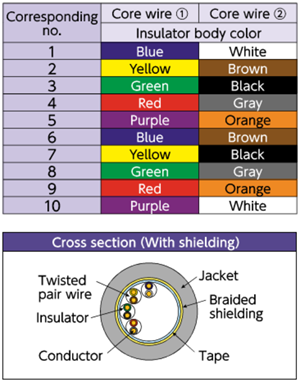
Layer stranded type configuration diagram
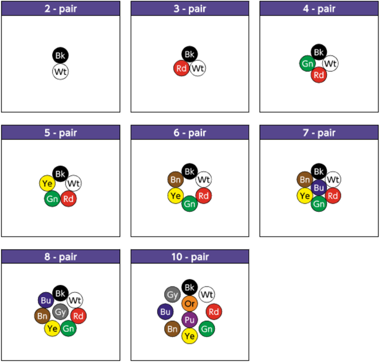
(Tables 1) Identification of core wires (layer-stranded types)
Twisted pair type configuration diagram*8
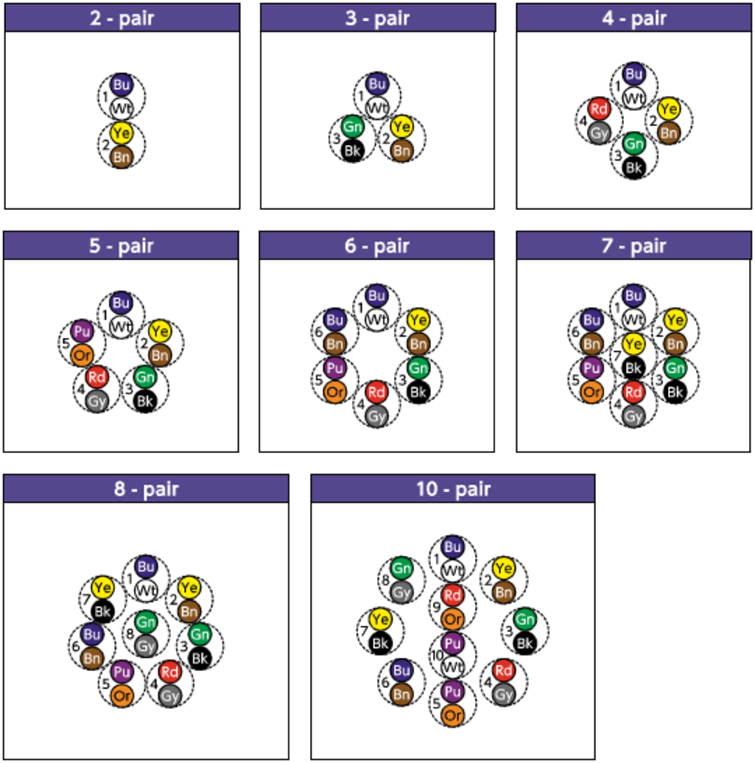
- *8 : The dotted circles indicate the pair configuration (twisted pairs) and the numbers indicate the pair numbers.
(Tables 2) Identification of core wires (Twisted-pair types)
- Inquiries regarding materials, consultations, and technology
- Inquiry from Web: Inquiry form